Measurement protocol
Mirko Kulig, 13.10.2008
- Objective
It is commonly known that a Tesla coil is capable of receiving electrical power wirelessly from a transmitting Tesla coil. The necessary conditions for this to happen are that the resonant frequency is set and that both coils are grounded.
The purpose of the measurement protocols herein exposed is to investigate the behavior of 2 Tesla transponders wirelessly coupled without ground.
2. Measured DC voltage as a function of the distance of the coils
I first want to measure the DC voltage at the receiving coil by gradually increasing the distance of the coils.
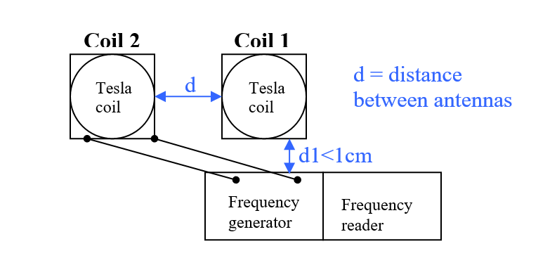
2.1 Experimental setup
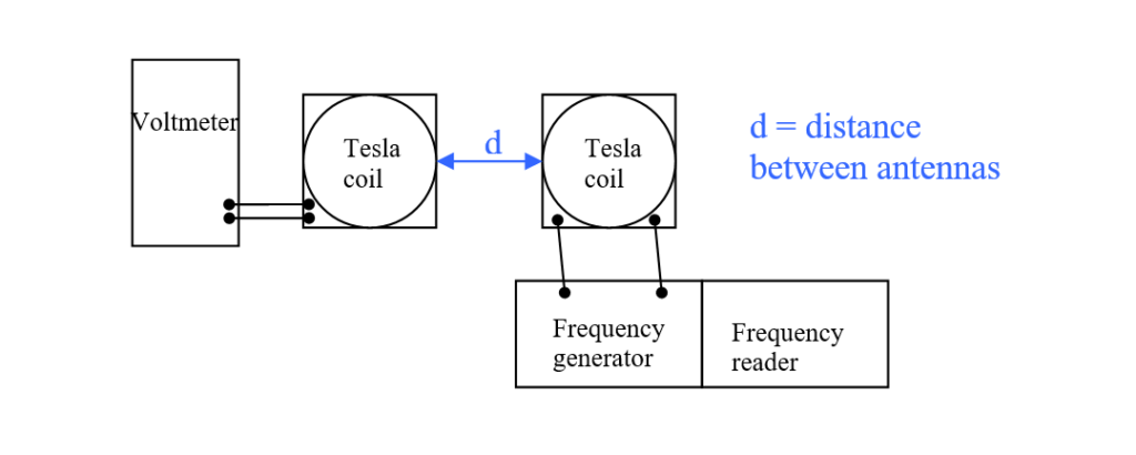
Used devices:
- 3 sets of Tesla coils (size A, B, C) with spherical antennas
- Voltmeter (Maxcom MX-210)
- Frequency generator (range 100 kHz – 13 MHz)
- Frequency reader
2.2 Determining the frequency of resonance
I have first determined the frequency of maximum voltage, which is:
- about 8.3 MHz for coils of size A
- about 13 MHz for coils of size B
- about 4.5 MHz for coils of size C
The coils also allow to move a jumper and to connect 2 LEDs to the output of the coils. I have tried to determine the frequency of maximum luminosity of the LEDs, which results to be:
- about 8.1 MHz for coils of size A
- could not be determined for coils of size B (probably because out of scale)
- about 4.45 MHz for coils of size C
Note: especially for the coils of size A, it was apparent that the frequency of maximum voltage and the frequency of maximum luminosity were not exactly the same.
2.3 Table of measured voltages
| Measured DC (mV) | |||
| distance between antennas (cm) | Coil of size A | Coil of size B | Coil of size C |
| 5 | 600 | 11 | 850 |
| 10 | 500 | 2 | 400 |
| 15 | 130 | 0 | 130 |
| 20 | 33 | 17 | |
| 25 | 9 | 5 | |
| 30 | 5 | 3 | |
| 35 | 2 | 2 | |
| 40 | 1 |
2.4 Graph of measured voltages
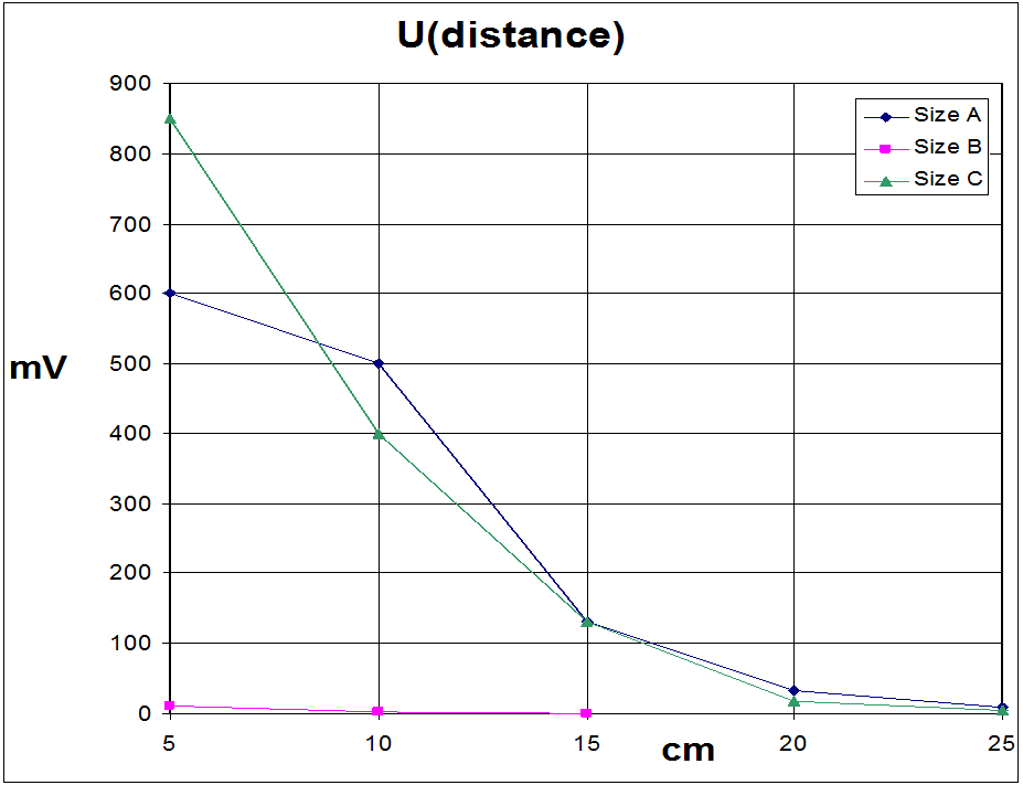
Table and graph clearly show a similar behavior for all coil pairs. The voltage measured at the receiving coil rapidly decreases when increasing the distance between the coils.
Regarding the coils of size B, I think that the actual resonant frequency (for the scalar component of the wave) was above the maximum frequency generated by our frequency generator, therefore I wasn’t able to measure higher values.
In the comparison between coil A and coil C, C has a higher voltage when the two coils are close, but decreases faster than coil A, which starts with voltage values which are not as high as those measured for coil C.
Anyway, it has to be kept in mind that our voltmeter is not a high quality device, and often the values written into the table were the empirically determined average of the relatively high oscillations of voltage that were measured each second. Variations, in some cases, would amount to up to 100 mV between the highest and the lowest measured values.
3. Measured DC voltage as a function of the frequency
When moving the frequency of the generator up and down for a constant distance of the coils with the jumper set to “LED”, especially with the coils of size A, it clearly appears that there are 2 maximums, one of which is more luminous than the other. Thus, I tried to measure the voltages with increasing frequency.
3.1 Table of measured voltages
Distance between the antennas: 5 cm
| Measured voltage (mV) | |||
| Frequency (MHz) | Size A | Size B | Size C |
| 2.3 | 1 | ||
| 2.5 | 1 | ||
| 2.7 | 3 | ||
| 2.9 | 7 | ||
| 3.1 | 18 | ||
| 3.3 | 77 | ||
| 3.5 | 166 | ||
| 3.7 | 220 | ||
| 3.9 | 210 | ||
| 4.1 | 280 | ||
| 4.3 | 480 | ||
| 4.5 | 860 | ||
| 4.7 | 560 | ||
| 4.9 | 55 | ||
| 5.1 | 0 | ||
| 5.5 | 1 | ||
| 5.7 | 4 | ||
| 5.9 | 10 | ||
| 6.1 | 20 | ||
| 6.3 | 50 | ||
| 6.5 | 70 | ||
| 6.7 | 80 | ||
| 6.9 | 84 | ||
| 7.1 | 80 | ||
| 7.3 | 85 | ||
| 7.5 | 110 | ||
| 7.7 | 160 | ||
| 7.9 | 235 | ||
| 8.1 | 490 | ||
| 8.3 | 560 | ||
| 8.5 | 450 | ||
| 8.7 | 180 | ||
| 8.9 | 70 | ||
| 9.1 | 4 | ||
| 9.3 | 1 | ||
| 11.9 | 0 | ||
| 12.1 | 2 | ||
| 12.3 | 8 | ||
| 12.5 | 10 | ||
| 12.7 | 11 | ||
| 12.9 | 11 | ||
| 13.1 | 10 | ||
| 13.3 | 8 | ||
| 13.45 | 8 |
3.2 Graph of measured voltages
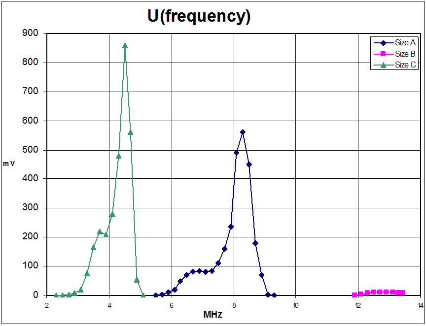
As the graph clearly shows every coil pair has its own frequency of resonance. Furthermore, when increasing the frequency, there is at first a partial rise in the measured voltage, which then stays quite constant for a certain range of frequencies, then to quickly rise to the maximum peak after which the measured voltage again becomes zero. This behavior is similar for the coils of size A and C, and I assume that, if we could reach higher frequencies with our frequency generator, the same behavior would be observed also for the coils of size B.
3.3 Comparison between measured voltages and luminosity of the LEDs
The following comparison has only been done for the coils of size A, since with this size the phenomenon was more apparent.
As has already been said before, the frequency of maximum voltage (8.3 MHz) didn’t perfectly match the frequency of maximum luminosity of the LED on the receiving antenna (8.1 MHz). This phenomenon has further been investigated.
To do so, while increasing the frequency with the jumper set to “LED”, an empirical value has been given to the luminosity of the LED, only to show the general behavior. (Unfortunately I don’t have a Lux meter..).
In this case, the maximum luminosity was given a value of 2, and when the LED was off, a value of zero was given.
I thus drew a graph of comparison between the measured voltages and the sensation of luminosity determined with the above procedure.
In order to allow a comparison, both series of values have been normalized to 1.
3.4 Graph of comparison between measured voltages and LED luminosity
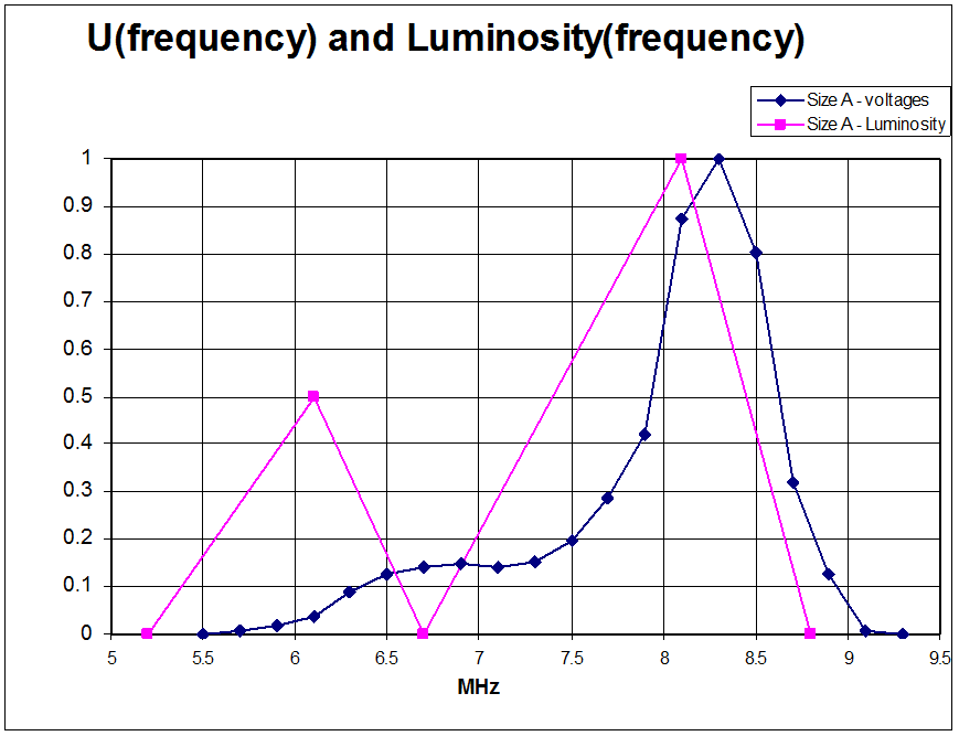
As the graph shows, the LED has 2 maximums at the frequencies of 6.1 MHz and 8.1 MHz. Considering that the LED has a threshold value, for voltages below which it doesn’t turn on, I can explain the small incongruences observable for the frequencies below and above the peaks. But what is really surprising, is that after the first maximum (6.1 MHz), for increasing frequencies the LED again gets off (at 6.7 MHz), while the measured voltages either stay constant or increase.
This behavior has been observed and reproduced more than once, always obtaining the same results.
The only way I could find to explain this behavior is again the low quality of the voltmeter. The best way to really test this behavior would be by using an oscilloscope, which I unfortunately don’t have.
3.5 Other observations
The 2 peaks are observed also when the two coils are appropriately grounded. As of Dr. Meyl’s theory, the first peak corresponds to the resonant frequency of the electromagnetic transverse wave, whereas the second peak corresponds to the scalar wave resonant frequency.
I could partially confirm this by the fact that, when the coils are working at the scalar wave resonant frequency, just by getting closer with one hand to either antenna, the luminosity of the LED decreases until it completely turns off when the distance between the antenna and our hand is about 3-5 cm.
On the other hand, when working at the transverse wave resonant frequency, this phenomenon is not observed, or is observed at a much lesser degree.
I explain this with the fact that scalar waves are directional, and tend to redirect all field lines towards a similarly resonant body, and with the “instable” resonance created in our setup without grounding, I assume than when getting close enough with a part of the physical body, actually all field lines from the emitting antenna tend to bend towards our body, which goes into resonance with it. This fact is also confirmed by a sensation of skin electricity that I experienced on the approaching hand, as well as a headache which arises after many hours of experimenting.
In the case of the transverse wave resonant frequency, the phenomenon is not observed because, as it’s well known, this kind of waves propagate in all directions and experience little disturbance by the presence of a resonant body.
4. Experiment with a coupling of the antennas through inducted resonance
While experimenting on groundless coupling, an interesting phenomenon has been observed, which might be of further interest.
I proceed on the description of said experiment.
4.1 Experimental setup
This time, the second tesla coil (Coil 2, usually used as the receiver) was connected to the frequency generator, while the first one (Coil 1, usually the transmitter) was left very close to the frequency generator.
It could be observed, that at a frequency of 6.3-6.4 MHz, the LED on Coil 1 would turn on, even if with a very dim light.
When increasing the distance of Coil 2, the LED on Coil 1 would not turn off, as was observed in the experience of point 2 of this document. It would simply slightly decrease its luminosity up to a distance of 1 m, but going farther would not further influence its luminosity.
The maximum distance between the coils was brought to 3 m (maximum length of the cables), without any further important decrease of luminosity of the LED on Coil 1. Various objects were interposed between the 2 coils (human body, TV), with no decrease of luminosity. When approaching a hand to one of the coils, the LED would turn off completely only when the distance became less than a few cm.
I tried to measure the DC voltage on Coil 1, but no measurable value was found (U<1 mV).
The only explanation I could give to this behavior is that, through direct induction of Coil 1 from the frequency generator, a weak but nonetheless important coupling could be established between the two coils which enabled a transmission of electricity from Coil 2. This explanation was partially confirmed by the fact that, when unplugging one of the wires that connected Coil 2 to the frequency generator, the LED on Coil 1 would completely turn off.
5. Conclusion
This series of experiments was carried out with the purpose of investigating the behaviour of 2 Tesla transponders coupled without ground.
The experiments have shown that:
- It is possible to transmit wirelessly electrical power without grounding of the coils at a very short distance (up to a maximum of 40 cm between transmitting and receiving antennas)
- The transmitted electrical power decreases with increasing distance
- the different frequency of resonance of the different coils (sizes A, B, C) has been verified
- the 2 frequencies of resonance (scalar wave resonance, transverse wave resonance) have been visually verified (luminosity of the LED), but the measured DC voltages as a function of the frequency have not shown exactly the same behavior as the LED; this fact needs further investigation with proper equipment, but until that I assume it is due to inaccuracies of the measuring equipment at my disposal (Voltmeter)
- the difference of behavior of the scalar wave compared to the transverse wave has been verified by the fact that an approaching human body was able to cause disturbances in the “instable” coupling of the antennas due to lack of grounding in the case of the scalar wave resonant frequency, whereas almost no disturbance was noted when working at the resonant frequency of the transverse wave
- it is possible to transmit electrical power without wires and without grounding of the coils at a distance of at least 3 m when the receiving coil is close to the frequency generator